Contact Information: Click on "Home," email [email protected], or phone 707-822-7300 (California) or 541-469-7300 (Oregon). Email administrative inquiries to ma[email protected].
ABOUT THIS PAGE: I began posting to this page on January 20, 2013. The white number that precedes the photo title (in green capital letters) is the BGC job number. Some jobs contracted in 2012 did not start until 2013. Some much older jobs are still active today. Please visit the site as the year develops! Click on a photo to enlarge it. I last posted images on December 20, 2013. On 1/12/2015 I did a light edit.
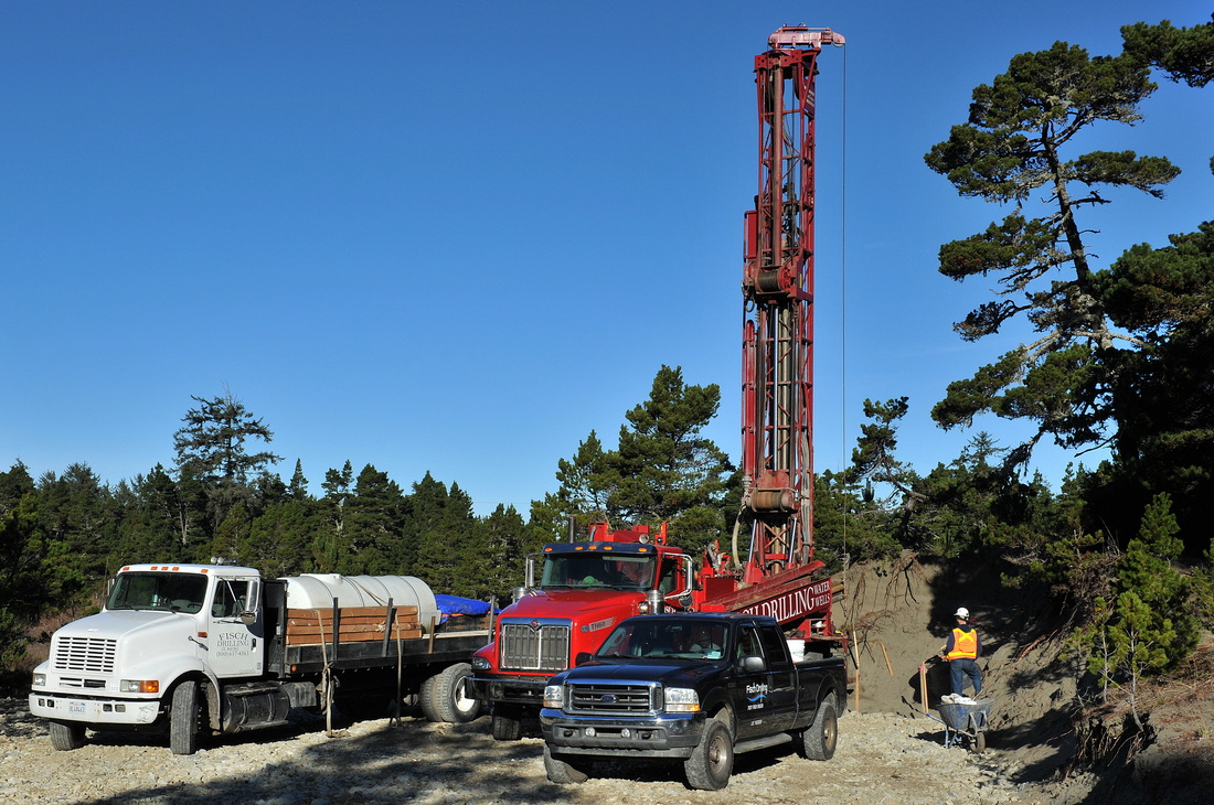
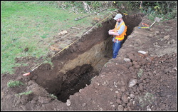
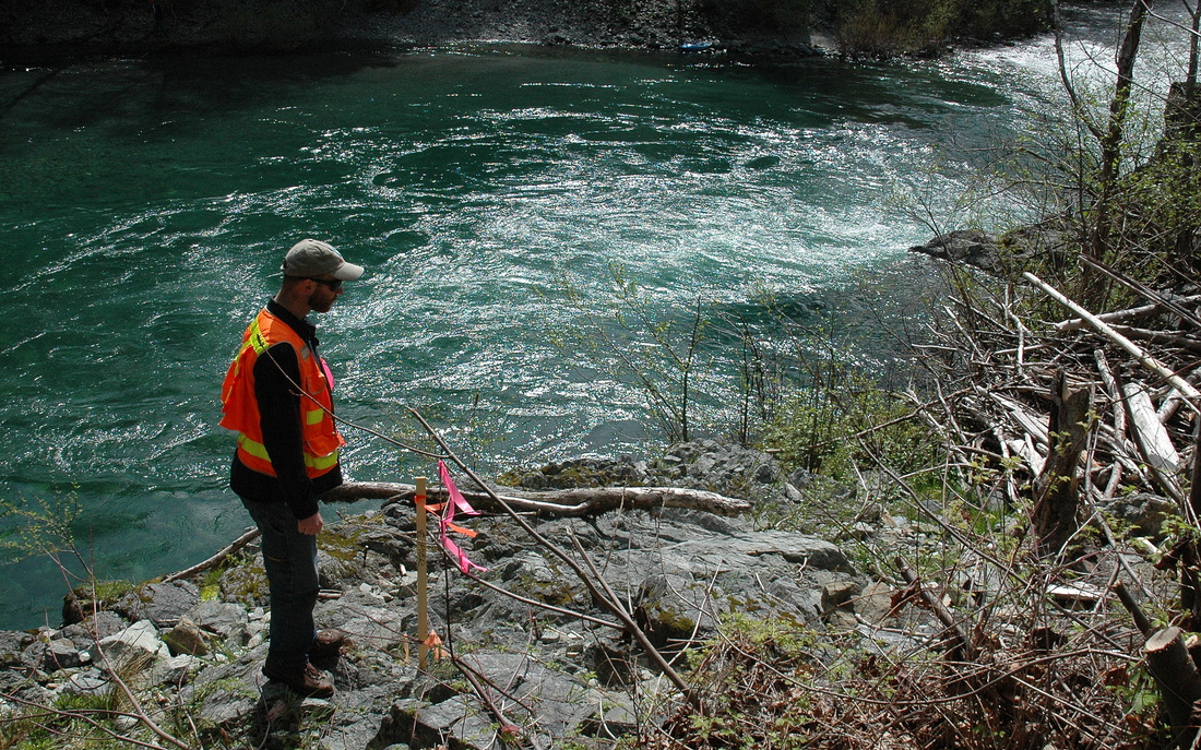
#13-010. SETTING A GROUNDWATER MONITORING WELL. BGC Staff Geologist Dylan Caldwell monitors the installation of a ~70-ft-deep monitoring well the Del Norte Solid Waste Management Authority is going to use to sample water quality and determine the groundwater flow direction near the closed solid waste disposal facility. We monitored the installation of two wells, one deep and one shallow. We completed grain size analysis, borehole logs, well installation diagrams, and a final report. and soon will prepare finale borehole logs and well installation diagrams. The DNSWMA now needs to decide how to proceed.
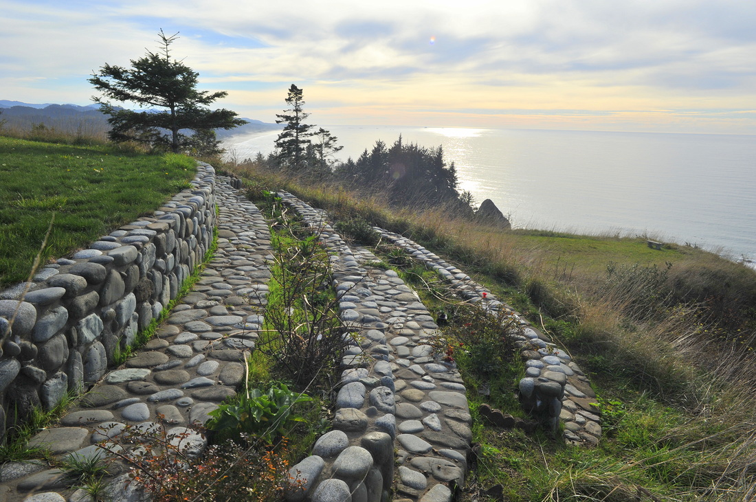
#13-023. ROCK WALLS. These walls struck me as too pretty to be ignored. The former homeowner built them (or had them built).
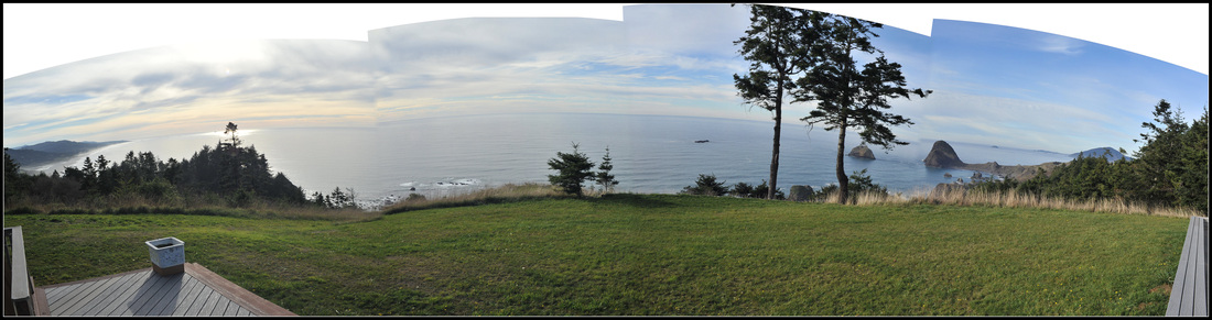
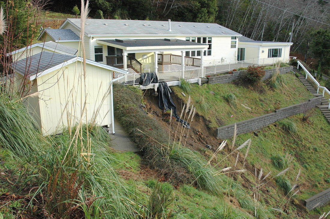
#13-023. ANOTHER DAY IN PARADISE IN CURRY COUNTY, OREGON! A potential buyer of a "$100,000 house with a Million Dollar view" hired us to assess the risk to the home from "everyday," static instability and from the future Csz earthquake. Slopes below the lawn change from 50% to 70% to >100% (45 degrees) and lead to US 101. We traversed the slopes south, west, and northwest of the home to observe geomorphic landforms, bedrock type, and conifer trunk deformations. We delivered a verbal assessment, our client purchased the property, and, if requested, we will write a "Geotechnical Realty Disclosure Report" for the client's file or to support a future sale.
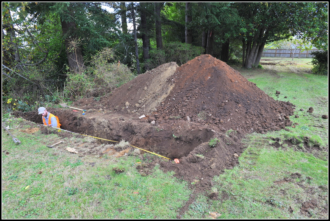
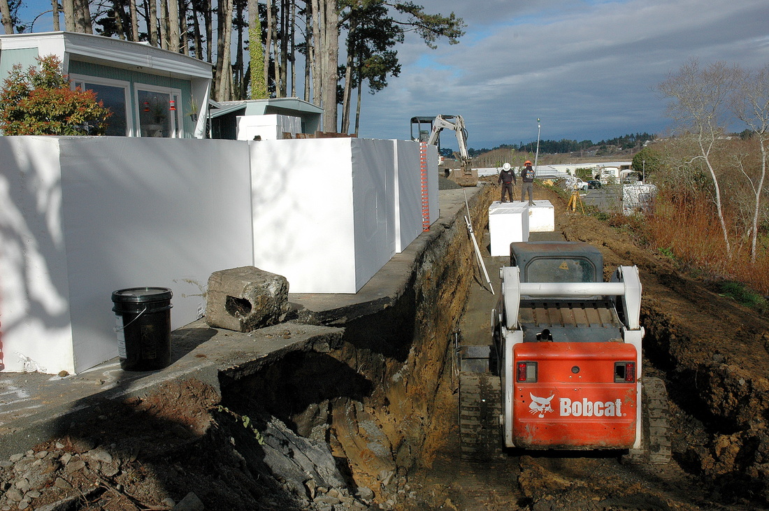
#13-022. HOW SAFE IS THIS TERRACE EDGE? BGC Staff Geologist Dylan Caldwell is logging the sidewall of a shallow trench we excavated at the break-in-slope (see next photo). Our goal is to determine, via material analysis and factor-of-safety calculations, an appropriate setback for either a road or homes, depending upon the developer's decision. We completed slope profiles, test pit and borehole logs, factor-of-safety stability calculations, and a summary report with alternative setback lines. The design team will use our report to plan the development.
#13-022. TEST PIT WALL. The gravel, topsoil around it, yellow soil above it, and dark brown soil above that are all uncompacted fills pushed over the original edge of the terrace. We excavated multiple test pits along the break-in-slope on this job site and each exposed a different fill geometry. Dylan is in the safe end of an unshored test pit because there the walls are competent and the pit is shallow. If the walls had been unstable either he would not have entered the pit or we would have installed temporary hydraulic shores. We didn't enter the other end of the pit as it posed an unacceptable level of risk.
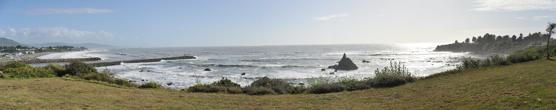
#13-020. WHAT A VIEW! Our clients wanted to purchase a home with this commanding view of the groins bordering the mouth of the Chetco River (and they did). Before they committed, because of a slope failure (a block topple) on the neighboring lot to the north, they had us inspect the bluff top and assess the risk and probable type and size of future failures. We delivered a verbal report and written reiteration and they completed the purchase. Later they purchased the property and hired us to provide a site-specific report for a proposed addition (see #14-025).
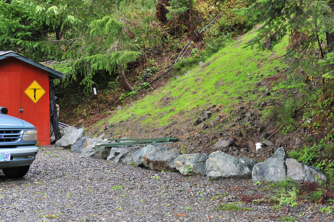
#13-021. HOLDING BACK A BAD REPAIR. This slope has failed several times. The last repair excavated into the slope and then backfilled with a local bedrock that included far too much clay. The material creeps and might slide, potentially striking the home. We studied the site and prepared a Work Plan governed by budgetary considerations. It calls for the instillation of a drainage- control structure and gabions (rock-filled wire cages) to partially buttress the toe and act as a retaining structure. UPDATE: The client had a contractor complete the work we recommended. Then he hired us to review the completed installation and write an "as-built" report (see #14-042).
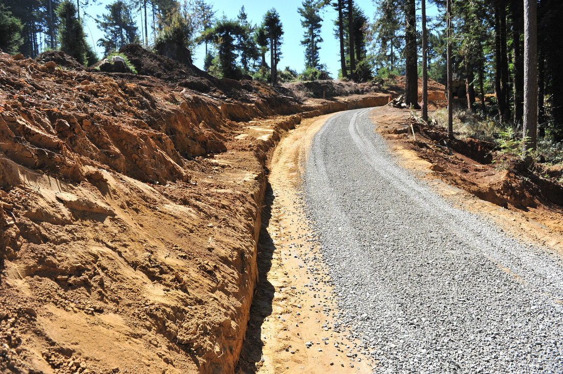
#10-018. READYING FOR WINTER 2. Higher up the road, our client is completing cutbank excavations and shaping and is graveling the road. Soon he will put erosion-control BMPs in place. We inspected the road when the BMPs were in place. As usual for this client, he had everything in order.

#10-018. READYING FOR WINTER 1. Our client has laid out preliminary forms for a low ornamental wall (with tiebacks) that will border the road, and trucks have begun graveling it to provide an over-wintering surface. We make episodic inspections of the progress of construction and provide on-demand consulting if issues arise.

#13-019. QUICK MUD! This pool of sandy mud alongside this home is nearly 5 ft deep and extends under the foundation. It formed only recently when a subtle change in the local groundwater throughflow pattern caused a spring to develop here. Our job is to decide how to remove the mud without undercutting the home, how to stabilize the adjacent failing bank, and how to connect an existing overwhelmed drain (buried in mud in this photo) to a functioning drain just around the back corner of the home. We completed a Work Plan and a local contractor successfully completed the repairs.
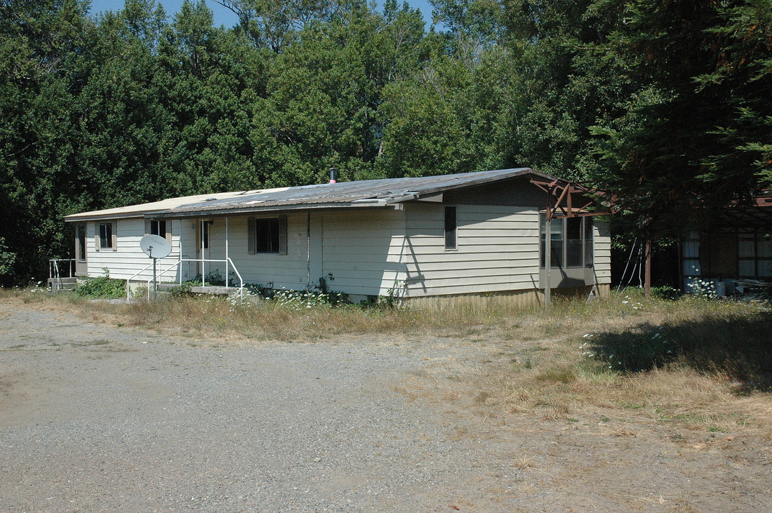
#13-018. HOW EASY IS THIS? Our client wants to tear down this ancient manufactured home (recently badly damaged by a windstorm) and build a small cabin. The site conditions are superlative so, unless the County demands more, he needs no more than a simple letter. How refreshing! Report Finished. Client's project is underway.

#13-013. THREE TEST PITS IN A ROW, AND EACH ONE IS DIFFERENT. I can't see any farther under the ground than you can. Here's a narrow little lot that one would assume is fairly similar underground. Nope. The far test pit exposed deeply weathered argillite bedrock (a GC in the Unified Soil Classification System). The middle one: mostly subsoils. The near pit? Sopping wet topsoils, subsoils, and fills. Fortunately, the project is not particularly soil sensitive so these vastly different conditions do not pose a significant problem. Report completed.
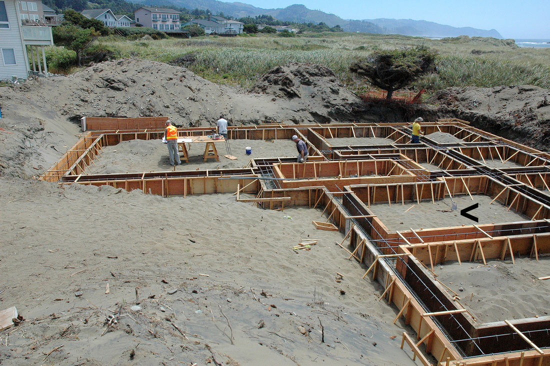
#13-007. BUILDING ON SAND. Staff Geologist Dylan Caldwell reviews construction plans to determine the required embedment of the bottom of the grade beams. In an usual construction method, this home will have a massive grade beam supporting reinforced cast-in-place concrete piers tied together at the top by glulam beams. Workers will flood sand back over the concrete grade beams and CIP piers. The FEMA-defined flood elevation here in the Rogue Shores Subdivision north of Gold Beach, OR, is 16 ft MSL, but our research suggests that water conceivably could rise to 19.5 ft MSL and cause scouring under exceptionally adverse storm conditions. We previously did a geologic hazards / foundation soils report for the home (#12-038). Here the bottom of the formed grade beams will be at 12 ft MSL; the top, 14 ft MSL; and the top of the CIP piers, 17 ft MSL. Workers will bury that part of the foundaion will sand (flooded to compaction), and timber, with break-a-way walls, will raise the design FF elevation to 23.33 ft MSL. On the day we did our inspection (7/17/2013), we hand-augered a borehole to the top of the groundwater table. We hit it at ~5.2 ft below the subgrade, or elevation 6.8 ft MSL, on an out-going tide. We issued an as-built certification letter (for submittal to the county) and the home construction is well underway.

#13-015. A SPECTACULAR VIEW TO THE NORTH, BUT PRETTY HIGH RISK. We first worked on this site in 2002 (BGC #02-074). We made a topographic map, inspected the bluff, drilled deep auger holes, and excavated several deep trenches across suspect ground features within the trees on the west side of the hilltop. The features are youthful scarps with down-to-west (normal) displacement. They are older than the trees, because the tress are plumb (for the most), but the trees are young: 40-50 years old, most likely. We recommended that the client construct a small home setback from the nearest scarp, using a 40-ft-deep foundation with the west edge of the home cantilevered. After 11 years, construction is about to start. We have been hired to provide a geologic addendum if necessary and to monitor the construction of the cast-in-place concrete piers (or vibration-emplaced I-beams). Plans for a cabin-style home are being developed.

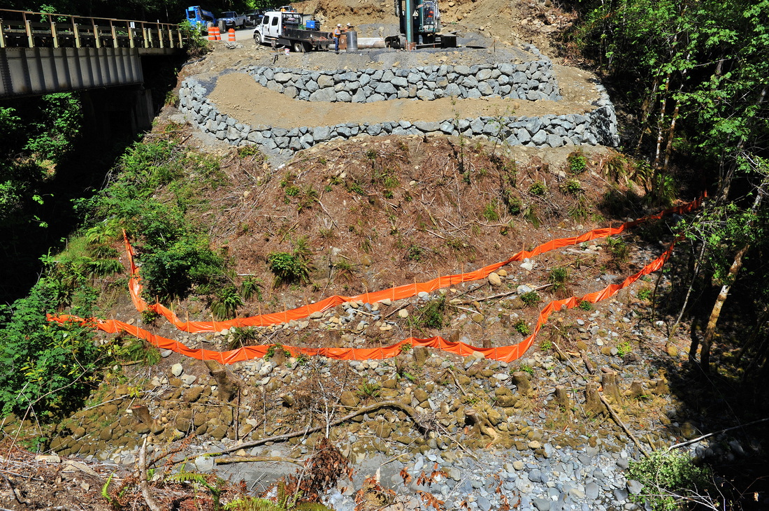
#13-004 (again). GREAT EROSION-CONTROL WORK, aka, BEST MANAGEMENT PRACTICES. This is a shot of the upgrade abutment of the new Hurdy Gurdy Bridge on South Fork Smith River Road. The day-glow orange "ribbons" are silt fences that will catch fine sediment if it washes downslope from the construction site above. The work is well done (but we had nothing to do with it). Our job monitoring the construction of the piers is done. We issued certified borehole logs and transmitted many rock samples to the job overseer.
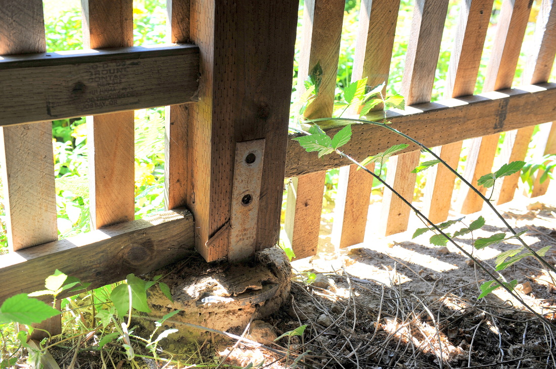
#13-014. SLOPPY WORK. Workers releveled the deck of this home but didn't bother to put bolts back into the 8x8 posts that hold up the deck (and edge of the roof). It's no big deal statically, but the wrong earthquake could cause significant damage to the deck and roof because of the omission of these and numerous other bolts. The selling homeowner has called the contractor back to finish the work properly. By now the new owners have moved in.
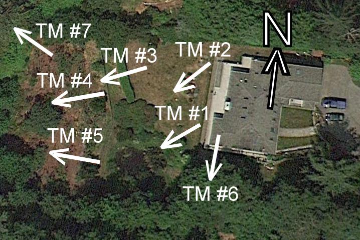
#08-044. TILTMETERS APLENTY! We have been monitoring ground movements at this upper-end Trinidad, CA, home since 1998. This photo shows the direction of orientation of seven of the eight tiltmeters we have installed onsite. Each tiltmeter is located about at the base end of the arrow shaft (not the point). TM #6 is inside the home on a slab floor. We set TM #7 recently to monitor an active landslide on the adjacent property to the north (see the photo below) and TM #8 near an encroaching bluff top failure that is out of view southwest of TM #5. In addition to the tiltmeters, we have two slope inclinometers onsite, and eight crack monitors on interior stem walls accessed from the crawl space. To date the monitoring data have allowed us to conclude the home is not at risk. However, TM #7 is moving pretty fast and we expect a lot out of TM #8. Although we monitor biannually, we just issued a special report in response to a nearby M4.9 earthquake that caused two new foundation cracks and registered movement on two of the crack monitors.
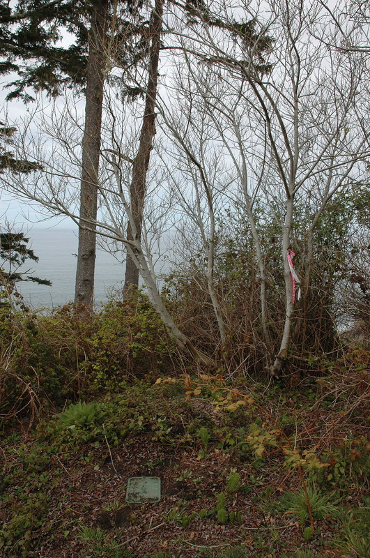
#08-044. THE FAST MOVER. This is the tiltmeter TM #7 installation location at the Trinidad home (see photo above). The tiltmeter is mounted on an in-ground installation and is protected by the valve box. The two Doug firs are leaning to the northwest (into the photo) because the ground they are on is beginning to fail into the adjacent landslide, which is behind them, progressing upslope (to the right). The slide is in late Pleistocene marine terrace sediments, but the Franciscan melange bedrock the sediments rest on is failing itself so is triggering the terrace edge failure. The rotation of the tiltmeter, which is about 30 ft from the left lateral margin of the slide, has vacillated. Sometimes it tilts toward the northeast (right) and sometimes it backtilts (toward the viewer). It won't surprise us if one winter the landslide takes away the trees and the tiltmeter. It wouldn't be the first tiltmeter we've lost to an angry winter ocean. We monitor this tiltmeter (plus TM #3, #4, #5, and now #8) more frequently than the others.
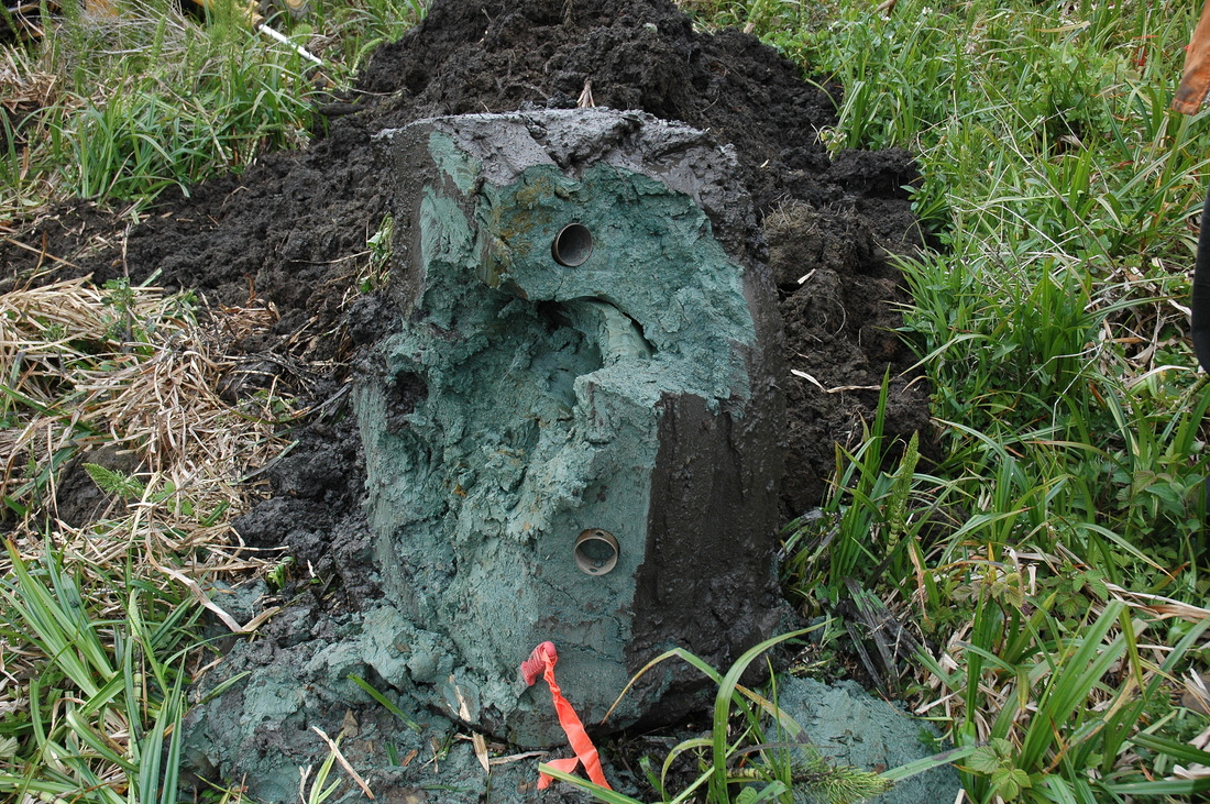
#12-041. AND IT'S NOT PHOTOSHOPPED! This backhoe bucket of clay and clayey sand came from a marine terrace sequence resting on the 105,000-year-old abrasion platform in Crescent City, CA. The soil is incredibly blue because it was below the water table for millenia. The surface of this mass came out of the ground muddy brown (note the color to the right of the brass-colored circle). We drove brass tubes into the soil to collect "undisturbed" samples for a density determination. Amazingly, the outside surface of hand samples bagged in sealed Ziplocs turned an equally intense olive green overnight. This bucket of soil came from the shallow surface in the alignment for a new road, Hangar Road, at the Crescent City airport. Report Completed.
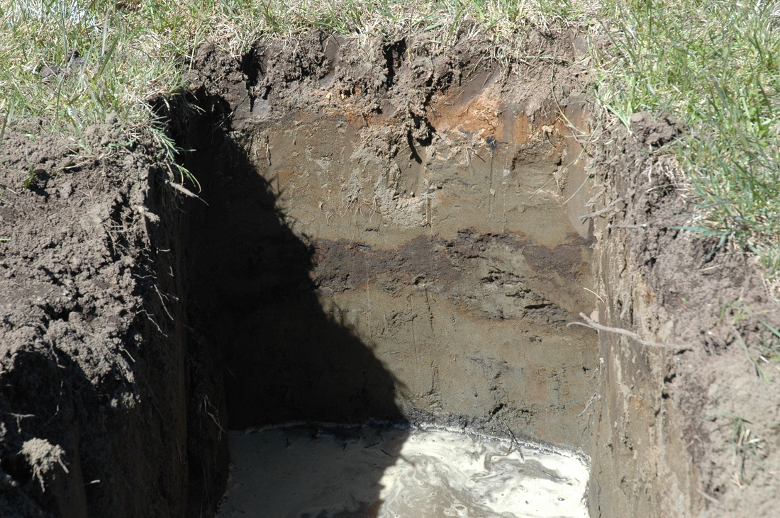
#13-005. TO REMOVE AND REPLACE OR NOT. Our client, URS, is designing the terminal and parking apron (as well as runway safety areas) for Del Norte County's Jack McNamara Airport. This photo shows the west end of a backhoe test pit that exposes a thin topsoil-based fill overlying fine sand fill obtained from local sand dunes. Although the sand compacts well from water flooding alone, there are pockets of organic-rich topsoil within it, and it is resting on a foot (more or less) of topsoil (the dark brown horizon). Such heterogeneities introduce options and complicate decision-making about the terminal foundation / foundation-soil treatment. We dug, logged, and sampled test pits, sent samples to an outside lab for special tests, and issued a report. Report Completed.
lick here to edit.
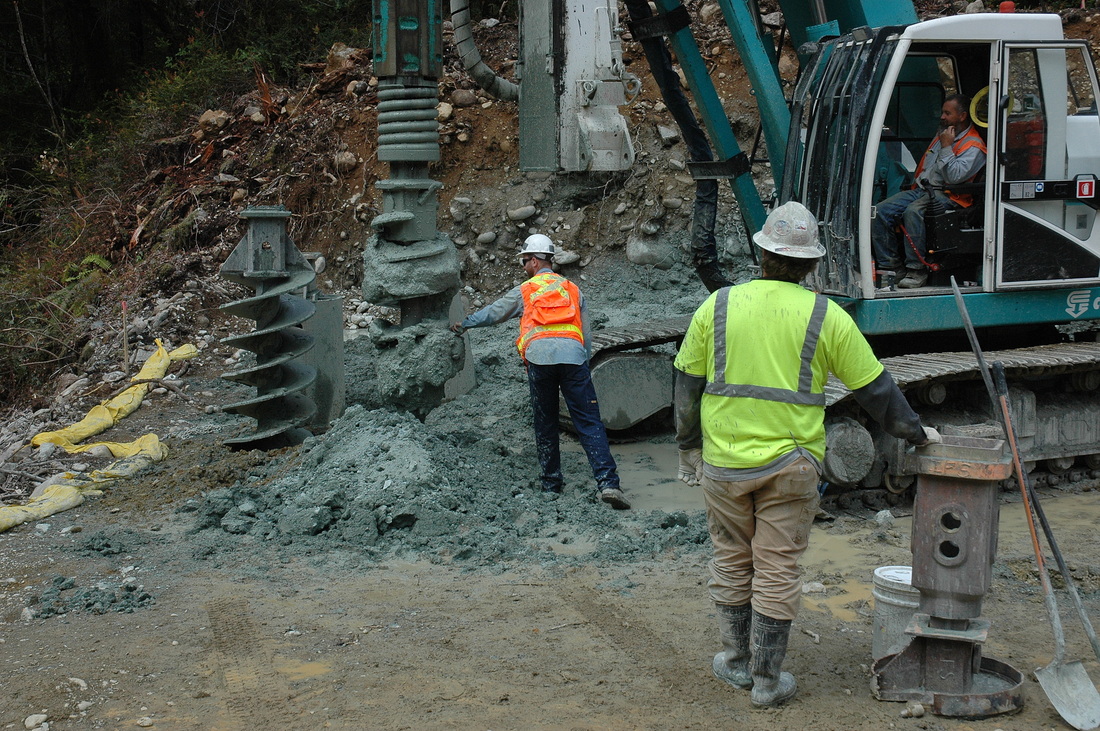
#13-004. Here's BGC Staff Geologist Dylan Caldwell collecting a sample from the auger of the drill in the photo below. The bedrock here is variably serpentinized gabbro. The terrane is part of the ophiolitic sequence of Del Norte County. We completed our work in July. See other photos in this year's work.
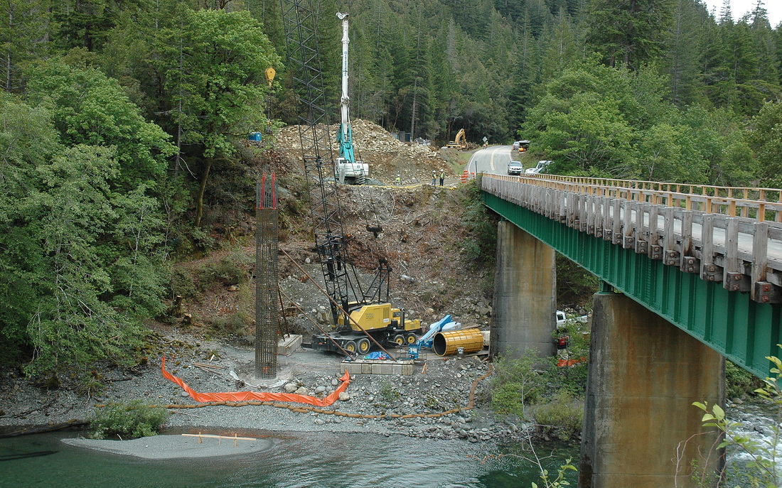
The crane is holding the top rebar cage of pier two for the new Steven Memorial Bridge. The drill in the background is working on one of the four abutment shafts at that end of the new bridge.
#13-004. NEW SOUTH FORK SMITH RIVER BRIDGES! BGC Staff Geologist Dylan Caldwell looks at the geologic setting (serpentinized ultramafic terrane) for the north pier of a new Steven Memorial Bridge on the South Fork Smith River. If things go as planned, he will be monitoring the drilling of the boreholes for the bridge piers and abutments and those for a new Hurdy Gurdy Bridge. There the boreholes will pierce Galice Formation lithologies, mainly slate. Drilling is scheduled to start in May. Salmon were spawning in the river as I took this photo. The ridge is now complete.
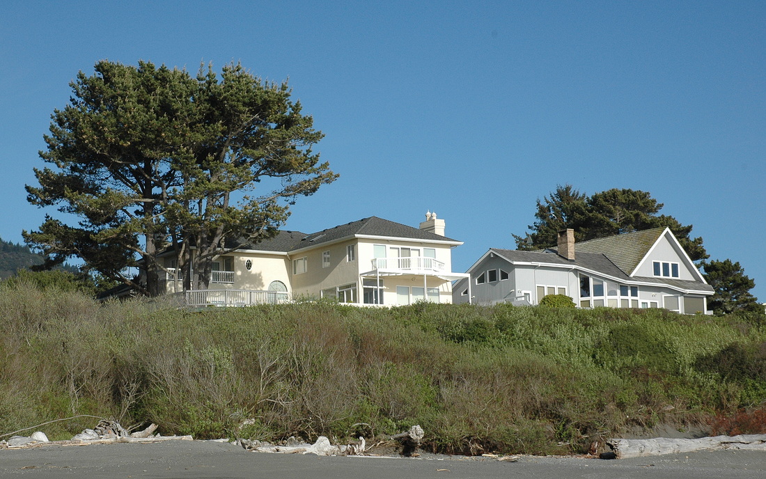
#13-006. WHAT GEOLOGIC HAZARDS COULD AFFECT THIS BEAUTIFUL SEASIDE HOME IN HARBOR, OREGON? Our client, the potential buyer of the home on the left, hired us to review the site geology, grounds, driveway and walks, and foundation exterior to qualitatively evaluate the potential for geologic hazards to affect the property. We completed our review, provided a verbal discussion, and then issued a report about soil creep, marine erosion, bluff instability, seismic shaking, and tsunami run-up hazards and risks. Happily for all concerned--sellers, buyers, realtors, and the consulting geologist, the hazards did not intimidate the buyers. Work completed.
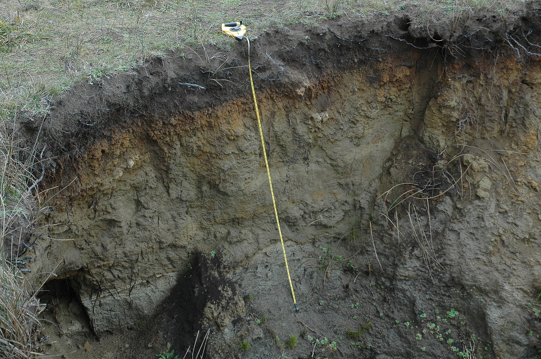
#12-039. UPLIFTED MARINE TERRACE ON A 105,000-YR-OLD ABRASION PLATFORM. This is a view of part of the sea cliff along the north end of Pebble Beach Drive in Crescent City, CA. The measurement location is just out of view in the air photo below. The yellow measuring tape drapes over a thin organic topsoil overlying a strongly oxidized subsoil. The oxidation lessens with depth. The underlying littoral marine sands rest on the Plio-Pleistocene Saint George Formation, a fossiliferous siltstone and fine sandstone. Here the St. George Fm. dips to the northeast as the southwest limb of a syncline, so the bedrock surface, an abrasion platform, is ~20 ft deeper under the airport terminal. The boreholes we drilled for the new alignment of Dale Rupert Road at the Jack McNamara airport pass through sand dune fill and into these units. We have delivered all three road reports.
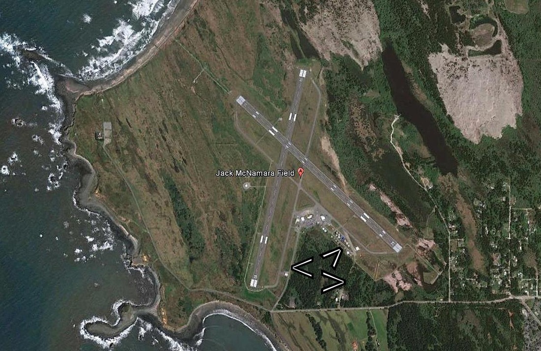
#12-039. JACK McNAMARA AIRFIELD, POINT ST. GEORGE, CRESCENT CITY, CA. This is a Google Earth image of the Del Norte Co. airport. The three "V"s point, from left to right, to Dale Rupert Drive, a proposed new Hangar Road, and a dirt road that will become Ag Road. BGC is providing fieldwork, lab data, and geotechnical reports (3) to support the new road construction. Del Norte Co. engineers will design the roads. The road work is a part of a multi-million dollar, decade-long airport upgrade project. We completed all of our road reports.
GRAPHICS from our work on the CRESCENT CITY AIRPORT (below). The next two figures are from our report on Dale Rupert Road (see aerial photo above). The first shows a topographic map, provided by Del Norte County, with boreholes by us and others. The second figure is a cross-section from south to north (left to right) of the soil horizons in the alignment. Our draftsman's awesome.
| 3a_dr_fig_2_boreholes_on_topo_final.pdf |
| 3c_dr_fig_4_x-sectin.pdf.pdf |
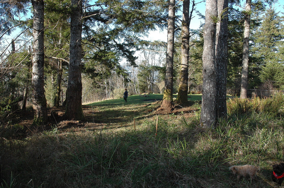
#13-003. AND YOU SHOULD SEE THE VIEW TO THE WEST! We worked here in 1998, who then sold, and 15 years later we are writing an addendum for the new owners to assure the County that the geologic conditions still support the construction of a SFR on a site with a commanding view. We are making suggestions to our client, who is very much amenable to strengthening the home foundation to better survive the coming CSZ earthquake. Doodle (black Brussels Griffon) and Cubby (the blonde) are for scale. Wife Marilyn in the distance. A Valentine's Day photograph. Addendum completed. Our clients constructed the detached garage / bonus room this summer.
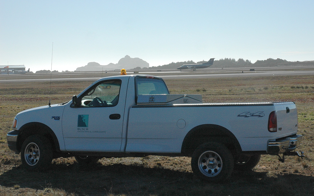
#12-034. BORING PHOTO; COOL WORK SITE. We were hired to determine the soil stratigraphy (layer pattern) off the ends of two runways at the Crescent City airport in order for our client to construct Runway Safety Areas (extensions of the pavement, for those "oops" situations all fliers dread). Our job: hand-auger boreholes, log soil types, and report on soil characteristics so the project engineers could decide what type of materials to import and what site-preparation must be done. Report finalized and the client has asked for additional support at the terminal footprint. See #13-005, above.
#12-017. HUMBOLDT COUNTY'S FIRST GEOFOAM APPLICATION? We're not sure. We know it's been used as light structural fill in buildings (rather than heavy aggregate), and that Caltrans used it in a landslide on US 101 in Del Norte County just south of Crescent City. But we think this might be its first use in the county to replace a failing road edge (see #12-017 site photo in 2012 Jobs). We issued as as-built construction monitoring report for submission by the client to the State regulatory agency.
click here to edit.
#12-044. TOO MUCH WATER TOO QUICKLY! This is yet another shot of yet another landslide that occurred following the 6-7+ inches of rain that fell in 10 hours in the Brookings, OR, area late on November 20th and in the wee hours of the 21st, 2012 (also see #12-040 and #12-043 in 2012 Jobs). Our client, an insurance company, hired us to determine if their insured's drainage-control efforts caused a landslide on the downslope neighbor's property. This isn't the insured's home or the neighbor's, but the photo is more impressive than any of the ones we took of the site itself (brush and visibility issues). Misdirected runoff from upslope driveways poured onto this home's backyard, ran around (and possibly under) the home, and "blew out" the ground as a debris slide. This home was a few hundred feet from the site we studied and this landslide was one of five in the immediate area. Report issued: Our opinion is that it was a high groundwater table and high pore water pressures caused by the excessive rainfall that triggered the debris slide below the insured's home, not runoff from the insured's roof. Also see the map of the area, next. The landslide in the photo is slide #4. UPDATE: The downslope neighbor has threaten litigation against the insured's insurance company. We wrote a second detailed report that counters assertions by the neighbor's consulting geologist. Everyone is waiting to see what will happen next.
| safeco-bgc_12-044_-_01.30.13.pdf |